Angular Measurement, Bevel Protractor, Universal Bevel Protractor, Vernier Bevel Protractor, Optical Bevel Protracor, Sine Bar, Spirit Level, Clinometers, Angle Gauge, Angle Slip Gauge, Insert Angle Gauge
Introduction:
Angular measurement is another important element in measuring. It
involves the measurements, two types of angle measuring devices are used. They
are angle gauges corresponding to slip gauges and divided scales corresponding
to line standards. The most common instrument is sine bar. Instruments for angular measurements:
• Protractors
• Dial bevel protractor
• Optical bevel protractor
• Sine bars
• Sine tables
• Sine centre
• Angle gauges
• Sprit level
• Clinometers
• Plain index centers
• Optical instruments for angular measurement such as auto
clinometer.
Bevel Protractor:
A bevel protractor is a graduated circular protractor with a
pivoted arm. The instrument generally used for measuring angle to an accuracy
of minutes is called bevel protractor.
Components of bevel protractor:
• Body:
The back of the body is perfectly flat and can be laid on the
surface plate without any support.
• Stock:
The working edge of the stock is about 90 mm long and 7 mm thick.
The working edge of the stock is essentially straight and maximum acceptable
concavity not more than 0.01 mm over the entire length.
• Blade:
It is about 150 to 300 mm long 13 mm wide and 2 mm thick. The ends
are bevelled at 45° and 60°. It is the movable part of the instrument and
straight upto 0.02 mm and parallel upto 0.03 mm over the entire length.
• Acute Angle Attachment:
It can be fitted and clamped into the body in any position. The
working edge should be flat within 0.005 mm and parallel to the working edge of
the stock within 0.0 15 mm over the entire length. The instrument is used to
check/ measure the following :
• Inside bevelled face of a ground surface
• V - block
• Measuring acute angle with special attachment.
• Types of bevel protractor:
• The different types of bevel protractors generally used are;
• Universal bevel protractor
• Vernier bevel protractor
• Optical bevel protractor.
Universal Bevel Protractor:
It is used for measuring and laying out of angles accurately and
precisely within 5 minutes. The protractor dial is slotted to hold a blade
which can be rotated with the dial to the required angle and also independently
adjusted to any desired length. The blade can be locked in any position.
Vernier Bevel Protractor:
The simple instrument, vernier bevel protractor, consists of a
base plate attached to the main body. An adjustable blade is attached to a
circular plate [Vernier is a part of it]. The adjustable blade can be locked in
any position and also can rotate freely along with the circular plate about the
centre of the main scale. The vernier has 24 divisions, having 12 divisions
marked on either side of 0 i.e., 11 main scale divisions made into 12 on the
Vernier, obtaining the least count of 5 minutes.
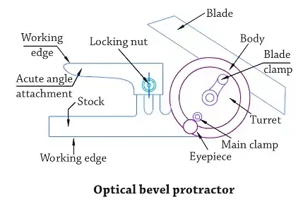
Optical Bevel Protracor:
In the case of optical bevel protractor, it is possible to take
readings upto approximately 2 minutes of arc. The provision is made for an
internal circular scale which is graduated in divisions of 10 minutes of arc.
Readings are taken against a fixed index line or vernier by means of an optical
magnifying system which is internal with the instrument. The scale is graduated
as a full circle marked 0-90-0-90. The zero positions correspond to the
condition when the blades are parallel to the stock. Provision is also made for
adjusting the focus of the system to accommodate normal variations in
eye-sight. The scale and vernier are so arranged that they are always in focus
in the optical system.
Sine Bar:
Sine bars used along with slip gauges form a very good device for
the precise measurement of angles. Sine bars are generally used to:
(i) Measure angles very accurately
(ii) Locate the workpiece to a given angle with very close limits.
Sine bars are made from high carbon, high chromium, corrosion
resistant steel, which is hardened, grounded and stablised. In this device, two
cylinders of equal diameter are attached at the ends. The axes of the cylinders
are mutually parallel to each other. At the same time, they are parallel to and
at equal distance from the upper surface of the sine bar. The distance between
the axes of two cylinders are 100 mm, 200 mm or 300 mm. Sine bars are of two
types, grade A and B depending on the accuracy of centre distance. Grade A sine
bars are more accurate and accurate up to 0.01 mm/m of length. Grade B sine
bars are accurate upto 0.02 mm/m of length. Holes are provided on the body to
reduce weight and for easy handling.
Principle of Sine Bar:
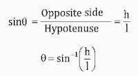
The operation of sine bar is based on trigonometry. For setting a
given angle, one roller of the sine bar is placed on the surface plate and slip
gauges are placed under the second roller as shown.
If h and l could be measured accurately, θ can be also obtained
accurately. The value h is built-up by slip gauges and the value ‘l’ is
constant for a given sine bar.
Constructional features of sine bar:
The two rollers must have equal diameter and should be equal
cylinders. The two rollers must be parallel to each other and also to the upper
face. The precise centre distance between the rollers must be known. The upper
face of the bar must have a high degree of flatness.
Spirit Level:
The spirit level is a simple form of mechanical measuring device.
It is mainly used for static levelling, yet it can be an angle measuring
instrument of high precision with a wide variety of applications. It is a
convenient means of determining the location of the horizontal plane through a
point. The principle of its working is that the surface of a still liquid is
level. This consists of a glass vial ground so that the longitudinal section of
the inner surface is a circular arc. The tube is filled with a liquid of low
viscosity, except for a small air space. The tube is sealed and mounted in a
brass tube. The air bubble is always at the highest point, due to gravitational
force. The bore of the via] is an arc of a circle so that the movement of the
bubble is a constant. The bubble will, move proportionate to the tilt
[vertical] of the vial. Under the action of gravity, the bubble moves to the
highest part of the tube, where it comes to rest. When the bubble is at the
middle of its run, the axis of the level is horizontal and so is the base of
the instrument.
The construction features of a precision spirit level. If the
level is tilted through a small angle θ, the bubble will move a distance along
the tube corresponding to the angle θ. When the base of the level is horizontal
[OB] the bubble is at C. If the base is tilted through a small angle θ, [to
OB1] the movement of the bubble is d, where the angle COD = θ.
d/R = θ [radians]
h/L = θ [radians]
h/ L = d/ R
The sensitivity of the spirit level is defined as the angular
value of one division. The angle through which the axis must be tilted to make
the bubble travel between adjacent graduations on the scale. Sensitivity is the
capability to exhibit small deviations from horizontal. The sensitivity of the
level is given by the displacement of the bubble for the given tilt of the
tube, which is given by d = i.e., for a given inclination of the spirit level
[h/L], if R [radius of the vial] is more, the sensitivity is more or the
displacement of bubble is proportional to the radius of the vial. If the radius
of curvature of the vial increases, the sensitivity also increases.
Clinometers:
A clinometer is a special case of the application of spirit level.
In clinometer, the spirit level is mounted on a rotary member carried in a
housing. One face of the housing forms the base of the instrument. On the
housing, there is a circular scale. The angle of inclination of the rotary
member carrying the level relative to its base can be measured by this circular
scale. The clinometer is mainly used to determine the included angle of two
adjacent faces of workpiece. Thus for this purpose, the instrument base is
placed on one face and the rotary body adjusted till zero reading of the bubble
is obtained. The angle of rotation is then noted on the circular scale against
the index. A second reading is then taken in the similar manner on the second
face of workpiece. The included angle between the faces is then the difference
between the two readings. Clinometers are also used for checking angular faces,
and relief angles on large cutting tools and milling cutter inserts. These can
also be used for setting inclinable table on jig boring machines and angular work
on grinding machines etc., The most commonly used clinometer is of the Hilger
and Watts type. The circular glass scale is totally enclosed and is divided
from 0° to 360° at 10' intervals. Subdivision of 10' is possible by the use of
an optical micrometer. A coarse scale figured every 10° is provided outside the
body for coarse work and approximate angular reading. In some instruments worm
and quadrant arrangement is provided so that reading upto 1' is possible. In
some clinometers, there is no bubble but a graduated circle is supported on
accurate ball bearings and its is so designed that when released, it always
takes up the position relative to the true vertical. The reading is taken
against the circle to an accuracy of 1 second with the aid of vernier.
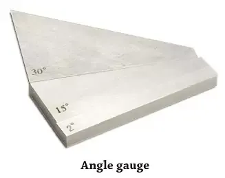
Angle Gauge:
Angle gauges are used for;
(i) Setup workpieces for desired angle
(ii) Measuring working angles.
This angle gauge are generally used for high precision work. The
faces of this gauge blocks are highly polished flat surfaces to acheive high degree
of accuracy. These angle gauges are wedge like in shape and made up of hardened
steel. These are available in the following three series;
First series : 1°, 3°, 9°,27°and 41°
Second series : 1’, 3’, 9’ and 27’
Third series : 3”, 6", 18” and 30”.
These blocks are placed one over other to increase overall block
angle. Each blocks are marked with V to indicate the direction of the block.
Angle Slip Gauge:
An angle gauge is a hardened steel block approximately 75mm long
and 1 mm wide which has two lapped flat working faces lying at a very precise
angle to each other as shown.
Angle gauges are supplied in sets and can be wrung together to
form desired angles. The angle gauges are supplied in set of thirteen pieces in
one box as given in table It also includes a square block.
These, together with a square block, enable any angle between B
degrees and 360 degrees to be constructed to within 1.5 seconds of the nominal
value by a suitable combination of gauges. Each angle gauge is a wedge, thus
two gauges with their narrow ends together provide an angle which is the sum of
the angles of the individual gauges. Subtraction of angles is obtained when the
narrow ends are opposed as shown.
Each angle gauge is marked with ‘V’ which indicates the direction
of included angle. To add the angles, all ‘V’ should be in same line and to
subtract angle, ‘V' marks should be in opposite direction. For example, to
measure the angle 43°24’ 1 2", the following set of angle gauges are
required.
The total of 7 angle gauges required as mentioned in the above
table and arranged as shown in fig.
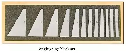
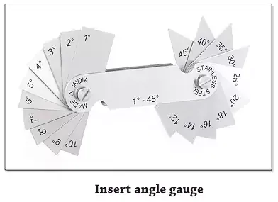
Insert Angle Gauge:
An insert angle gauge measures the angle of a fixed or worked
object relative to a larger object.
These are made of hardened steel. The measuring face are lapped
and polished to a high degree of accuracy and flatness. This angle gauge are
used to set up any angle to the nearest accuracy of 3 minutes. An angle gauge
set consist of thirteen separate angle gauge block which are collectively
pivoted at one end.
END










0 Comments