Linear Measurement, Introduction to measurement, Vernier calipers, Digital caliper, Micrometers, Outside micrometer, Inside micrometer, Screw thread, Depth micrometer, Vernier micrometer,Vernier height gauge, Vernier depth gauge, Comparators, Screw pitch gauge, Wire gauge, Plate gauge, Radius gauge, Fillet gauge, Template gauge, Feeler gauge, Slip gauge or Gauge blocks
Introduction to measurement
Measurement systems are mainly used in industries for
quality control management. Often quality control engineers are applying some
of the measuring systems such as linear -and angular measurements. These
measurements are very much useful to compare the actual measurements with
already existing standard measurements. In practice, we come across many
parameters to be measured in a given situation. For example, in a pneumatic
drilling, we have to measure the pressure at which air is, the speed at which
the drill operates, the depth through which drilling has been done and so on.
Linear measuring instruments:
The linear measurement includes the measurement of lengths,
diameters, heights and thickness. The basic principle of linear measurement is
that of comparison with standard dimensions on a suitably engraved instrument
or device. The various devices used for measuring the linear measurements are;
• Vernier calipers
• Micrometers
• Slip gauge or gauge blocks
• Comparators.
The Vernier principle:
The basic principle of the Vernier is that the smallest unit
of size to which a Vernier can be read is equal to the difference in the length
between the divisions of the two scales. The magnification on the Vernier scale
is given by two scales sliding over each other. The eye can detect which
divisions on one of them are smaller than those on the other. It is the fact
which enables us to read a Vernier to 0.02 mm accuracy.
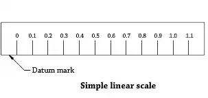
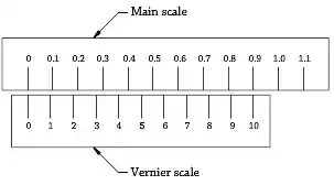
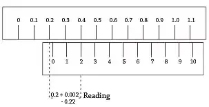
Figures show the vernier principle being used to determine
the reading. Figure shows the main scale with the datum line marked.
Figure shows the main scale and Vernier scale with
graduations. The Value of 1 main scale is 0.1 unit. In Vernier scale 9 such
units are taken and divided into 10 equal parts. Hence the Value of 1 Vernier
scale is, 0.9/10 = 0.09 units
Now, by applying the Vernier principle, the smallest unit of
size is 1 M.S.D. — 1 V.S.D. [i.e.] 0.1 -0.09 = 0.01 unit.
Definition of the least count:
The least count is the smallest possible measurement that
can be taken with the precision instrument. The zero of the Vernier scale is
between 0.2 to 0.3 units on the main scale and number 2 graduation of the
Vernier scale is coinciding with the 4th division of the main scale.
Measurement of reading:
Example 1

0.3 mm

0.3 mm
'0' of vernier is to the right of '0' of the main scale and
lies between '0' and 1st division of the main scale. The 3rd division of the
vernier scale coincides with a division on the main scale. Hence measurement is
0 mm + 3 X 0.1 mm = 0.3 mm.
Example 2

44.4 mm

44.4 mm
'0' of the vernier scale lies between the 44th and 45th
divisions of the main scale and the 4th division of the vernier scale coincides
with a division of the main scale.
Hence the measurement is 44 mm + 4 x 0.1 mm = 44.4 mm.
'0' of the vernier scale lies between the 53th and 54th
divisions on the main scale and the 8th division of the vernier scale coincides
with a division on the main scale.
Hence measurement is 53 mm + 8 x 0.1 mm = 53.8 mm
Vernier caliper and its application:
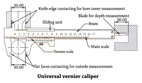
One of the precision instruments having the principle of
Vernier applied to it is the universal vernier caliper. The universal vernier
caliper is mainly used,
• To take outside measurement.
• To take inside measurement.
• To take depth measurement.
A universal Vernier caliper consists of a;
• Beam
• Fixed jaw for external measurements
• Sliding unit consisting of
» Movable jaw for external measurements
» Movable jaw for internal
measurements
» Blade for depth
measurement
• Main scale
• Vernier scale
• Fine adjustment screw
• Set of locking screws
All parts are made up of nickel-chromium steel, heat
treated. They are machined to high accuracy. They are stabilized to avoid distortion
due to temperature variations.
Constructional features:
The beam is the main part and the main scale graduations are
marked on it. The markings are in millimeters and every tenth line is drawn a
little longer and brighter than the other graduations and numbered as 1,2,3 ...
To the left of the beam the fixed jaws for external and internal measurements
are fixed as integral parts. The vernier unit slides over the beam. At the
bottom face of the beam a keyway-like groove is machined for its full length,
permitting the blade to slide in the groove. At the bottom right hand end, a
unit is fixed serving as a support for the blade ‘ when it slides in the
groove. The Vernier unit has got the Vernier graduations marked on it. The
movable jaws for both external and internal measurements are integral with
this. The fixed and movable jaws are knife-edged to have better accuracy during
measurement. When the fixed and movable jaws are made to contact each other,
the zero of the Vernier scale coincides with the zero of the main scale. At this position the blade will be in line with the right
hand edge of the beam. When the Vernier scale unit slides over the beam, the
movable jaws of both the measurements as well as the blade advance to make the
reading. To slide the Vernier unit, the thumb lever is pressed and pulled or
pushed according to the direction of movement of the Vernier unit.
The application of the universal Vernier caliper in taking
external, internal and depth measurements is shown in figure.
Advantage:
• No need to have separate precision instruments for taking
external, internal and depth measurements.
Disadvantages:
• Accuracy of reading depends on the skill of the operator.
• Losses its accuracy by constant usage as slackness in the
sliding unit develops.
• Cannot be used to measure components having deviations
less than +/-0.02 mm.
Digital caliper:
The digital caliper [sometime incorrectly called the digital
Vernier caliper] is a precision instrument than can be used to measure internal
and external distance accurately to 0.01 mm. The digital Vernier caliper is
shown in below figure.
The distance or the measurements are read from LED drawing.
The parts of digital calipers are similar to the ordinary vernier caliper except
the digital display and few other parts. Earlier versions of the type of
measuring instrument had to read by looking carefully at the inch or metric
scale and there was a need for very good eye sight in order to read the small
sliding scale. Manually operated Vernier caliper are remain popular because
they are much cheaper than the digital version. The digital caliper requires a
small battery whereas the manual version does not need any power source. The
digital calipers are easier to use as the measurement is clearly displayed and
also, by pressing inch/mm button the distance can be read as metric or inch.
The display is turned on with the ON/OFF button. Before measuring, the zero
setting to be done, by bringing the external jaws together until they touch
each other and then press the zero button. Now the digital caliper is ready to use. Always set zero position when turning on the display for the first time.
Graduations and reading of Vernier caliper
Vernier caliper:
The Vernier principle states that two different scales are
constructed on a single known length of line and the difference between them is
taken for fine measurements.
Least count of Vernier caliper:
The main scale divisions 9 mm are divided into 10 equal
parts in the Vernier scale
• One main scale division [MSD] = 1mm,
• Least count = 1 MSD - 1 VSD
= 1 mm - 9/10 = 0.1 mm
• The difference between one MSD and one VSD = 0.1 mm
Vernier Measurements:
The Vernier calipers are available with different
graduations and least counts. Reading measurements with a Vernier caliper, the
least count should be determined first.
The graduations of a common type of Vernier caliper with a
least count of 0.02 mm. In this, 50 divisions of the Vernier scale occupy 49
divisions [49 mm] on the main scale.
Example:
Main scale reading = 60 mm
The Vernier division coinciding with the main scale is the
28th division, value = 28 X 0.02 = 0.56 mm
Reading = 60 + 0.56 = 60.56 mm.
Micrometer
Micrometer:
It is a precision tool used to measure up to an accuracy of
0.01 mm. Various micrometers are,
• Outside micrometer
• Inside micrometer
• Screw thread
• Depth micrometer
• Vernier micrometer
Accuracy of calipers:
The accuracy of the measurement with calipers depends very
much on;
• The sense of touch while measuring the component.
• The accuracy of calipers used with steel rules is limited
to 0.5 mm.
Outside micrometer:
• The purpose of a metric micrometer is to read an accuracy
of 0.01 mm of an object
• It is available in various sizes.
• The principal parts of a micrometer are the frame, anvil,
spindle and the thread, sleeve or barrel and the thimble.
• There is a knurled collar or small lever on the frame to
lock the spindle in the barrel.
• In addition to this, a ratchet stop is provided to the
spindle in order to prevent a possible excess pressure on the screw treads.
• The sleeve or barrel is marked with the main scale in
full mm and half mm.
• The thimble bevel end is graduated with the thimble
scale.
• Fifty equal divisions are made on the circumference of
the thimble bevel end.
• Every 5"‘ division of the graduation is indicated
with the number.
• The spindle face is fitted with a carbide tip to resist
the wear.
• The spindle with the screw is attached to the thimble of
the micrometer.
• The corresponding threaded nut is fitted to the barrel or
sleeve of the micrometer.
• The other measuring face of the micrometer is the anvil,
which is normally fitted i with a carbide tip to resist the wear.
• The range of micrometers are 0 - 25 mm, 25 - 50 mm, 50 - 75,
75 - 100 mm etc.
• The spindle can be easily screwed down in the barrel.
• When the face of the anvil and the face of the spindle
are in contact, the 0 graduations of the index line and 0 graduation of the
thimble coincide with each other.
• The spindle may be withdrawn by rotating the thimble in
an anticlockwise direction.
• The thimble portion is knurled to provide a good grip for
holding as well as for rotating the spindle.
Inside micrometer:
• The inside micrometer is similar to an ordinary outside
micrometer but without the’ U‘ frame.
• The measurement is taken over the contact points. As the
thimble opens or closes, the contact points get opened or closed.
• The inside micrometer consists of a sleeve, thimble,
anvils, a spacing collar and extension rods.
• It is also equipped with a handle to measure deep bores.
• The least count of the instrument is also 0.01 mm.
• The inside micrometer is equipped with a 12 mm spacing
collar and 4 extension rods for measuring holes of ranges 50-75 mm, 75-100 mm,
100-125 mm and 125- 150 mm.
• The sleeve is marked with the main scale and the thimble
with the thimble scale.
• When the inside micrometer is closed [when zero of
thimble coincides with the zero of the barrel].
• It is capable of reading the minimum dimension of 25 mm.
• In addition to this, it is possible to read up to 38 mm
with the thimble opening to the extreme right.
• In order to read further higher ranges, a standard
spacing collar of 12 mm width is to be added.
• This facilitates the micrometer to read a maximum range
of 50 mm.
• Similarly, each extension rod has to be used without the
collar for measuring a minimum range up to 13 mm variation and with the collar
for a maximum range of measurements.
• A clamping screw is also provided to clamp the extension
rod firmly.
Depth micrometer:
• It is used to measure the precise depths of holes,
grooves and recesses by using interchangeable rods to accommodate different
depth measurements.
• When using a depth micrometer, you must make sure the
base of the micrometer has a flat, smooth surface to rest on and that it is
held firmly in place to ensure an accurate measurement.
• A set of extension rods is generally supplied.
• The range of sizes that can be measured with rod is
engraved as 0 - 25, 25 - 50, 50 - 75,75 - 100,100 - 125 and 125 - 150 mm.
• The extension rods can be inserted inside the thimble and
the sleeve.
• The extension rods have a collar head which helps the rod
to be held firmly.
• The measuring faces of the stock and the rods are
hardened, tempered and ground.
• The measuring face of the stock is machined perfectly
flat.
• The extension rods may be removed and replaced according
to the size of depth to be measured.
Screw thread micrometer:
• Is used to measure the pitch diameter of screw with
accuracy of 0.01 mm.
• It looks similar to outside micrometer.
• The screw thread micrometer has a 60-degree pointed
spindle and a double V-shaped swivelling anvil.
Vernier micrometer:
• Vernier micrometer is used to measure up to an accuracy
of 0.0001 inch.
• In addition to the thimble and sleeve graduations, it has
a vernier scale on the sleeve.
• The Vernier scale has 10 equal divisions running parallel
above the barrel mark in a space of 9 divisions of thimble.
• Each division of Vernier scale represents (0.009/10] =
0.0009 inch.
• The difference between one thimbie division and Vernier
scale division is [0.001 -0.0009] = 0.0001 inch.
• Reading on sleeve = 9 x 0.025 = 0.2250 inch
• Reading on thimble = 11 x 0.001 = 0.011 inch
• Reading on Vernier scale = 3 x 0.0001 = 0.0003 inch
• Size = 0.2363 inch
Depth & Height Gauges
Vernier height gauge:
A height gauge is a measuring device used either for
determining the height of work-piece.
These measuring tools are used in metal working to either set or measure vertical distances, the pointer is sharpened to allow it to act as a scriber and assist in marking out work pieces.
These measuring tools are used in metal working to either set or measure vertical distances, the pointer is sharpened to allow it to act as a scriber and assist in marking out work pieces.
Usage of Vernier height gauge:
• Accurate measurements are important in layout and
inspection work.
• Vernier height gauges are particularly suitable for
marking off accurate distances, and centre locations.
• The graduations and readings are the same as those of a
Vernier caliper.
Important parts of Vernier height gauge:
The main parts of a Vernier height gauge and their functions
are,
• Base:
It is the datum from which measurements and settings are
made. The underside of the base is hardened, ground and lapped.
• Beam:
It is similar to the beam scale of a vernier caliper and is
attached t0 the base.
• Vernier Slide:
This unit slides on the beam and carries the vernier plate,
locking screws, fine setting device and scriber. Vernier height gauges of some
are provided with a rack and pinion arrangement for moving the slide along the
beam. Vernier height gauges are provided with both straight and offset
scribers.
Zero setting of the Vernier height gauge:
• The offset scriber permits zero setting of the instrument
from the datum surface.
• While using a straight scriber, the zero setting of the
instrument is at a level above the datum surface.
• The zero setting is to be checked using the precision
round block, supplied along with the instrument.
• Vernier height gauges with which we can measure from the
datum surface without the special offset scribers are also available.
• The size of the vernier height gauge is stated by the
height of the beam.
• The most commonly used size has a beam of 300 mm height.
• Vernier height gauges are used with surface plates or
other accurate flat surfaces.
Vernier depth gauge:
• Works on the same principle of Vernier caliper.
• Designed for measuring the depth of blind holes and
slots.
• By using this instrument, the base is held firmly against
the reference surface.
• The blade is lowered into the hole until the blade
touches the surface of the hole.
• After tightening, the clamping screw is moved from the
hole and read in the same way as the vernier caliper.
Application of vernier depth gauge:
• A vernier depth gauge is a very commonly used precision
instrument for the measuring of holes, recesses, slots and steps.
• Its construction and method of reading are similar to
those of a Vernier caliper.
Parts of a vernier depth gauge:
• Base [1], Graduated beam [2], Clamping screw [3], Fine
adjustment mechanism [4] and Vernier scale [5].
• The base [Anvil] is the fixed unit and serves as a datum
for measurement.
• It also carries the Vernier scale and the fine adjustment
mechanism.
• The beam with the main scale graduations is the sliding
member or part.
• Fine adjustments for measurement are made after
tightening the clamping screw and the fine adjustment mechanism.
• The relief given at the end of the beam of some vernier
depth gauges is to avoid the seating in the corners of slots and to ensure
correct reading.
• Remove burrs, if any, before taking measurements.
• Excessive pressure on the beam, while taking measurements
will lift the base from the reference surface and will show wrong measurements.
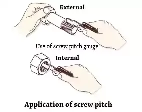
Screw pitch gauge:
A screw pitch gauge is used to determine the pitch of a
thread. It is also used to compare the profile of threads.
Constructional features:
• Pitch gauges are available with a number of blades
assembled as a set.
• Each blade is meant for checking a particular standard
thread pitch.
• The blades are made of thin spring steel sheets, and are
hardened.
• Some screw pitch gauge sets will have blades provided for
checking British standard thread [BSW, BSF etc.) at one end and the metric
standard at the other end.
• The thread profile on each blade is cut for about 25 mm
to 30 mm
• The pitch of the blade is stamped on each blade.
• For obtaining accurate checking while using the screw
pitch gauge, the full length of the blade should be placed on the threads.
Wire gauge:
• It consist of oblong plate having holes of different size
to receive different size wires.
• Each hole is stamped with a number which define the holes
and wire size.
• This stamped number starts from 1 to 80.
• This wire gauge also available in circular shape.
Plate gauge:
• Sheets are sold as flat, rectangular sheets of standard
size.
• It is specified using standard gauge numbers usually from
16 gauge down to 30 gauge.
• Sheet metal gauges refer to the thickness of a particular
type of sheet metal product.
• Larger the gauge number, lesser will be the thickness.
• Gauge is a single number measurement of the thickness of
the sheet.
• The equivalent thickness differs for each gauge size
standard, which were developed based on the weight of the sheet for a given
material.
• Micrometer and thickness measuring gauge is used to
measure sheet metal thickness.
• Standard gauge is used to check and separate coils.
Radius and fillet gauges:
• Components are machined to have curved formation on the
edges or at the junction of two steps. They are called radius and fillets.
• The size of the radius and fillet is normally provided on
a drawing.
• The gauges used to check the radius formed on the edges of
diameters are fillet gauges.
• The gauges used to check the fillets are called radius
gauges.
• They are made of hardened sheet metal each to a precise
radius.
• They are used to check the radii by comparing the radius
on a part with the radius of the gauge.
The other typical applications are:
• The radius and fillet gauges are available in sets of
several blades which fold into a holder when not in use.
• Each blade can be swung out of the holder separately, and
has its size engraved on it.
Template gauge:
• Template gauges consist of a set of steel or plastic pins
that are set tightly against one another in a frame which keeps them in the
same plane and parallel while allowing them to move independently,
perpendicularly to the frame.
• When pressed against an object, the pins conform to the
object.
• The gauge can then be used to draw the profile or to copy
it on to another surface.
Feeler gauge:
• These are thin steel blades hardened and ground to
various sizes.
• They consist of a number of small lengths of steel of
different thicknesses with measurements marked on each piece.
• Used for checking the clearance between two mating parts.
• Vanes are from 0.03 to 1 mm thickness.
Gauge block:
• Slip gauges are gauge blocks used as standards for
precision length measurement.
• It is used as a reference for the calibration of
measuring equipment used in machine shops, such as micrometers, sine bars,
calipers, and dial indicators.
• Gauge blocks come in sets of blocks of standard lengths.
• In use, the blocks are stacked end-to-end to make up the
desired length.
• Gauge blocks are the main means of length standardization
used by industry.
• These slip gauges are available in various sets with
different numbers.
• A particular size can be built-up by wringing individual
slip gauges together.
• Wringing is the act of joining the slip gauges together while building up to sizes.
• Wringing is the act of joining the slip gauges together while building up to sizes.
Selection and Determination of Slip Gauges for Different Sizes:
Uses of slip gauge:
Slip gauges are used,
• For precise measurement of parts.
• For verifying measuring tools such as,
(i) Micrometers
(ii) Comparators
(iii) Various limit gauges.
END








0 Comments