Grinding Machine, Purpose of grinding, Advantages of grinding, Disadvantages of grinding, Applications of grinding, Types of grinding, Surface grinding methods, Classification of grinding machines, Grinding wheel, Abrasives, Bond and bond materials, Grits, Grade, Structure, Selection of grinding wheels, Maintenance of grinding wheel
Introduction to grinding:
• Grinding
is metal cutting operation performed by means of a rotating abrasive wheel that
acts as a tool.
• This is
used to finish workpieces which must show a high surface quality, accuracy of
shape and dimension.
• The art of
grinding goes back many centuries. Over 5,000 years ago, the egyptains abraded
and polished building stones to hairline fits for the pyramids, columns and
statues were shaped and finished with a globular stone which abraded the
surface.
• Mostly
grinding is the finishing operation because it removes comparatively little
metal, 0.25 to 0.50mm in most operations and the accuracy in dimensions is in
the order of 0.000025 mm.
• Grinding
is also done to machine materials which are too hard for other machining
methods that use cutting tools.
• Many
different types of grinding machines have now been developed for handling
various kinds of work to which the grinding process is applicable.
Purpose of grinding:
• To bring
the component to close size.
• To obtain
required surface finish.
• To machine
very hard surfaces.
Advantages of grinding:
• The
surface finish obtained is superior.
• One of the
most dimensionally accurate machining processes.
• Hardened
components can be machined.
• Grinding
permits to machine light and delicate parts due to requiring little pressure.
• Surface
unevenness can be eliminated.
• Various
kinds of works can be grinded.
• Designed
geometrical configuration can be achieved.
• It removes
little material of order 0.25 to 0.50mm.
Disadvantages of grinding:
• Work
surface gets over heated.
• Wheel wear
results duplicate parts do not have the same dimensions.
• Grinding
is not suitable for heavy metal removing.
• For some
complicated parts grinding needs attention.
• Achieving
true parallelism requires skill.
• Achieving
concentricity needs attention.
• Achieving
true parallelism requires skill.
• Achieving
concentricity needs attention.
Applications of grinding:
• All cast
components require grinding.
• Welded
components require grinding.
• Crank
cases, forged components.
Types of grinding:
Grinding
operation can be classified into two different categories:
(i) On the
basis of quality of grinding;
• Rough
grinding or non precision grinding.
• Precision
grinding.
(ii) On the
basis of surface to be ground;
• External
grinding
• Internal
grinding
• Surface
grinding
• Form
grinding.
Rough grinding:
• The rough
grinding are snagging and off hand grinding where the work is held in the
operators hand.
• The work
piece is pressed against the wheel.
• Rough
grinding used where, the accuracy and surface finish are secondary factor.
• Some of
the application of rough grinding are, trimming the surface left by sprues and
risers on casting, grinding part line on casting, removing flash on forgings,
excess metal on welding etc.
Precision grinding:
• Precision
grinding concerned with producing good surface finishing and high degree of
accuracy.
• The wheel
or work both are guided in precision paths.
• Precision
grinding is followed after rough grinding.
Surface grinding methods
External cylindrical grinding:
• External
cylindrical grinding produces a straight or tapered surface on a workpiece,
shown on figure below.
• Workpiece
must be rotated about its own axis between centres as it passes lengthwise
across the face of a revolving grinding wheel.
Internal cylindrical grinding:
• Internal
cylindrical grinding produces internal cylindrical holes and tapers, shown in
figure below.
• The
workpieces are chucked and precisely rotated about their own axis.
• The
grinding wheel rotates against the sense of rotation of the workpiece.
Surface grinding:
• Surface
grinding produces flat surface.
• The work
may be ground by either the periphery or by the end face of the grinding wheel.
• The
workpiece is reciprocated at a constant speed below or on the end face of the
grinding wheel.
Form grinding:
• Form
grinding is done with specially shaped grinding wheel.
• That grind
the formed surfaces as in grinding gear teeth, threads, splined shafts, holes,
etc.
Centreless grinding:
• In this
process, the work is supported between grinding wheel and regulating wheel on
work rest blade.
• The
principle of centreless grinding is shown in figure.
• Used when
long slender bars are to be finished.
Classification of grinding machines
The grinding
machine can be classified as;
•
Cylindrical grinding machine
(i) External
cylindrical grinder
(a) Centre
type
(b)
Centreless type
(ii)
Internal cylindrical grinder
(a) Centre
type
(b)
Centreless type
• Surface
grinding machines
(i) Vertical
spindle
(a)
Reciprocating table
(b) Rotary
table
(ii)
Horizontal spindle
(a)
Reciprocating table
(b) Rotary
table
• Tool and
cutter grinding machines
• Special
grinding machines.
Cylindrical grinding machine:
A
cylindrical grinding machine is similar to the lathe, but on which a grinding
wheel is mounted instead of the single point cutting tool.
Plain
milling cutters are divided into;
• Base
• Table
• Headstock
• Tailstock
• Cross
feed, and
• Wheel
head.
Base:
• The base
or bed is the main casting that rests on the floor and supports the parts
mounted on it.
• On the top
of the base are precision horizontal ways set at right angles for the table to
slide on.
• The base
also houses the table-drive mechanism.
Table:
• There are
two tables-lower table and upper table.
• The lower
table slides on ways on the bed provides traverse of the work past the grinding
wheel.
• It can be
moved by hand or power within desired limits.
• The upper
table that is pivoted at its center is mounted on the top of the sliding table.
• It has
T-slots for securing the headstock and tailstock and can be positioned along
the table to suit the length of the work.
• The upper
table can he swivelled and clamped in position to provide adjustment for
grinding straight or tapered work as desired.
• Setting
for tapers upto ±100 can be made in this way.
• Steep
tapers are ground by swivelling the wheel head.
• Adjustable
dogs are clamped in longitudinal slots and they are provided at the side of the
lower or sliding table and set up to reverse the table at the ends of the
stroke.
Headstock:
• The
headstock supports the workpiece by means of a dead center and drives it by
means of a dog, or it may hold and drive the workpiece in a chuck.
Tailstock:
• The
tailstock can be adjusted and clamped in various positions to accommodate
different lengths of workpieces.
Wheel head:
• The wheel
head carries a grinding wheel and its driving motor is mounted on a slide at
the top and rear of the base.
• The wheel
head may he moved perpendicularly to the table ways, by hand or power, to feed
the wheel to the work.
Cross feed:
• The
grinding wheel is fed to the work by hand or power as determined by the
engagement of the cross-feed control lever.
• On
cylindrical grinding machines, the operation may he stopped automatically when
the workpiece has been finished to size.
• In one
method it uses an automatic caliper type gauging attachment to measure the
workpiece and stop the operation at the proper time.
Working of cylindrical grinding machine:
• The workpiece
is usually held between dead centers and rotated by a dog and driver on the
face plate as shown in figure.
• The work
may also be rotated about its own axis in a chuck.
• There are
four movements involved in a cylindrical centre-type grinding,
(i) The work
must revolve
(ii) The
wheel must revolve
(iii) The work
must pass the wheel
(iv) The
wheel must pass the work.
• They are
equipped with a mechanism which enables the grinding wheel to be fed in
automatically towards the work for successive cuts.
• Hand feed
is employed only in adjusting the wheel or starting the cut.
• A
provision is also made for varying the longitudinal movement of the work or the
wheel.
• Hydraulic
rather than mechanical controls are preferred on grinding machines to cause
minimum vibration.
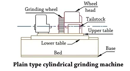
• Figure
illustrates schematically this machine,
• The
machine is similar to a centre lathe in many respects.
• A disc
type grinding wheel performs the grinding action using the peripheral surface.
• Both
traverse and plunge grinding can be carried out in this machine.
Traverse grinding:
• The work
is reciprocated as the wheel feeds to produce cylinders longer than the width
of the wheel face.
Plunge grinding:
• The work
rotates in affixed position as the wheel feeds in to produce cylinders of a
length equal to the width of the wheel.
• The
important advantage is that cylindrical shapes can be produced as easily as
straight cylinders in a single "plunge" of the wheel simply by
forming the periphery of the wheel.
Surface grinding machines:
• Surface
grinding machines are generally used for grinding flat surfaces. These machines
are similar to milling machine in construction as well as in motion.
• Some types
of surface grinders are also capable of producing contour surface with formed
grinding wheel.
• Basically
there are four different types of surface grinding machines characterized by
the movement of their tables and the orientation of grinding wheel spindles as
follows,
(i)
Horizontal spindle and reciprocating table
(ii)
Vertical spindle and reciprocating table
(m)
Horizontal spindle and rotary table
(iv)
Vertical spindle and rotary table.
• The
majority of surface grinders are of the horizontal table type. In the
horizontal type of machine, grinding is normally done by the periphery of the wheel.
• The area
of contact is small, and the speed is uniform over the grinding surface.
• Small
grain wheels can be used, and the finest finishes obtained.
• The
vertical type, surface grinders apply the face or side of the wheel, and cupped
cylindrical, or segmented wheels are used.
• The area
of contact may be large, and stoke can be removed rapidly. But a crisscross
pattern of grinding scratches are left on the work surface.
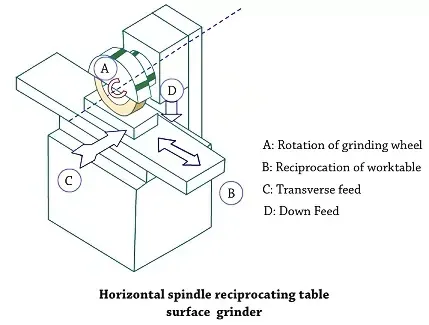
Horizontal spindle reciprocating table surface grinder:
• The block
diagram of a straight wheel horizontal spindle reciprocating table surface
grinder is shown in figure.
• A disc
type grinding wheel performs the grinding action with its peripheral surface.
Both traverse and plunge grinding can be carried out in this machine as shown
in figure.
Base:
• The base
has a column at the back for supporting the wheel head. The base also contains
the drive mechanisms.
Table:
• The table
is fitted to the saddle on carefully machined guide ways. It reciprocates along
ways to provide the longitudinal feed.
• T-slots
are provided in the table surface for clamping workpieces directly on the table
or for clamping grinding fixtures or a magnetic chuck.
• On some
machines, the table can also be moved in or out from the vertical column which
supports the wheelhead. This movement is known as cross- feed.
Wheelhead:
• The
wheelhead is mounted on the column secured to the base.
• It has
ways for the vertical slide which can be raised or lowered with the grinding
wheel only manually by rotating a hand wheel to accommodate workpieces of
different heights and to set the wheel for depth of cut.
•
Horizontal, crosswise movement of the wheel slide with the wheel, actuated by
hand or by hydraulic drive, accomplishes the cross feed of the wheel.
• The
grinding wheel rotates at constant speed - it is powered by a special built -
in motor.
Operation:
• The
workpiece reciprocates under the wheel, and the wheel or the table feeds
axially between passes to produce a fine flat surface.
• Wheel
downfeed determines depth of cut and final height of the piece from the table
to the wheel.
• The amount
of feed must only be equal to a few hundredth of a millimeters.
(i) For
example, steel is rough ground with a depth of cut between 0.02 and 0.05mm and
finish-ground with a depth of cut of 0.005 to 0.01 mm.
(ii) In the
case of grey cast-iron the depth of cut in rough grinding may be anything
between 0.08 and 0.15 mm and in finish grinding between 0.02 and 0.05 mm.
Horizontal spindle rotary table surface grinder:
• Surface
grinding in this machine is shown in figure.
• In
principle, the operation is same as that for facing on the lathe.
• This
machine has a limitation in accommodation of workpiece and therefore does not
have wide spread use.
• The
swiveling the worktable, concave or convex or tapered surface can be produced
on individual part as illustrated in figure.
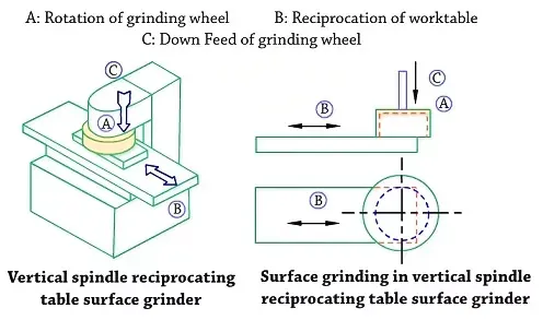
Vertical spindle reciprocating table surface grinder:
• This
grinding machine with all working motions is shown in figure.
• The
grinding operation is similar to that of face milling on a vertical milling
machine.
• In this
machine a cup shaped wheel grinds the workpiece over its full width using end
face of the wheel as shown in figure.
• This
brings more grits in action at the same time and consequently a higher material
removal rate.
Vertical spindle rotary table surface grinder:
• The block
diagram of a vertical spindle rotary table surface grinder is shown in figure.
• The
principal elements of this machine consists of a magnetic chuck which can be
moved under or away from the wheel for unloading and loading the work.
• Slide
which is mounted on horizontal bed ways.
• The
grinding spindle is mounted vertically on the face of a column and rotates in a
fixed position feeding only along its axis.
• The rotary
table travels beneath the wheel as grinding wheel rotates.
• This
combination of table travel and table rotation exposes the entire surface of
the workpiece to the wheel and eliminates the need for any lateral movement of
the wheel.
Tool and cutter grinding machine:
• Tool and
cutter grinders are used mainly to sharpen and recondition multiple tooth
cutters like reamers, milling cutters, drills, taps, hobs and other types of
tools used in the shop.
• With
various attachments they can also do light surface, cylindrical, and internal
grinding to finish such items and jig, fixture, die and gauge details and
sharpen single point tools.
• They are
classified according to the purpose of grinding, into two groups,
(i)
Universal tool and cutter grinders
(ii)
Single-purpose tool and cutter grinders.
Universal tool and grinders:
• Universal
tool and cutter grinders are particularly intended for sharpening of
miscellaneous cutters.
•
Single-purpose grinders are used for grinding tools such as drills, tool-hits,
etc.
• In large production
plants where large amount of grinding work is necessary to keep production
tools inpropercutting condition.
• In
addition, tools can be ground uniformly and with accurate cutting angles.
• A typical
tool and cutter grinder is shown in figure below,
• The
universal tool and cutter grinder has the following principal parts;
Base:
• The saddle
is mounted directly on the top of the base.
• It is
heavy, rugged and box-type.
• It carries
all other parts of the machine.
• It is made
up of heavy cast iron to absorbs impact load and vibrations during cutting
stocks.
Saddle:
• The saddle
is mounted directly on the top of the base.
• It moves
on antifriction ball bearings on hardened ways.
• The column
supporting the wheel head is mounted on the saddle and it can he moved up and
down and swivelled to either side.
• The saddle
also provides the means for moving the work forward and backward.
Table:
• The table
rests and moves on a top base which is mounted over the saddle.
• The top of
the base contains the gears and mechanism which control the table movement.
• The work
table is mounted on the sub-table which has T-slots for mounting the work and
attachments used on the machines.
• The work
table can be swivelled which enables the operator to grind tapers.
Headstock and tailstock:
• The
headstock and tailstock are mounted on either side of the table similar to
those on a cylindrical grinder.
• The
workpiece is positioned between the centres and driven exactly as in a
cylindrical grinder.
Wheel head:
• The wheel
head is mounted on a column on the back of the machine.
Grinding wheel:
• Three
different types of grinding wheels are extensively used in cutter grinding.
They are;
(i) The
"straight" or disc-shaped wheel
(ii) The cup
type in either the straight or flaring form
(m) The dish
type.
Centreless grinding machines:
• This
grinding machine is a production machine in which out side diameter of the
workpiece is ground.
• The
workpiece is not held between centres but by a work support blade.
• It is
rotated by means of a regulating wheel and ground by the grinding wheel.
• The
principal elements of an external centreless grinder are shown, Figure shows
the grinding wheel, regulating or back up wheel, and the work rest. Both wheels
are rotated in the same direction.
• The work
rest is located between the wheels. The work is placed upon the work rest, and
the latter, together with the regulating wheel, is fed forward, forcing the
work against the grinding wheel.
• The axial
movement of the work past the grinding wheel is obtained by tilting the
regulating wheel at a slight angle from horizontal. An angular adjustment of 0
to 8 or 10 degrees is provided in the machine for this purpose.
Through grinding:
• The
regulating wheel revolving at a much lower surface speed than grinding wheel
controls the rotation and longitudinal motion of the workpiece.
• The
regulating wheel is kept slightly inclined to the axis of the grinding wheel
and the workpiece is fed longitudinally as shown in figure.
Infeed grinding:
• Which is
similar to plunge grinding or form grinding.
• The
regulating wheel is drawn back so that workpieces may be placed on the
work-rest blade. Then it is moved in to feed the work ,against the grinding
wheel.
• This
method is useful to grind shoulders, and formed surfaces.
Endfeed grinding:
• Used to
produce taper, either the grinding wheel or regulating wheel or both are formed
to a taper.
• The work
is fed lengthwise between the wheels and is ground as it advances until it
reaches the end stop.
Advantages of centerless grinding:
• As a true
floating condition exists during the grinding process, less metal needs to be
removed.
• The
workpiece being supported throughout its entire length as grinding takes place,
there is no tendency for chatter or deflection of the work and small, fragile or
slender workpieces can be grounded easily.
• The
process is continuous and adapted for production work.
• No centre
holes, no chucking or mounting of the work on mandrels or other holding devices
are required.
• The size
of the work is easily controlled.
• A low
order of skill is needed in the operation of the machine.
Disdvantages of centerless grinding:
• Work
having multiple diameter is not easily handled.
• In hollow
work, there is no certainly that the outside diameter will be concentric with
the inside diameter.
• This
process is not suitable for large size workpiece.
• This
process is useful only for large volume production.
Grinding wheel:
• A grinding
wheel is a rotating abrasive wheel used to ground the workpiece.
• Grinding
wheel is made up of crushed hard particles [abrasives] and embedded in a matrix
called the bond.
• The sharp
edges of the abrasive particles act as acting edge to ground the workpiece.
Abrasives:
• An
abrasive is a substance that is used for grinding and polishing operations.
• It should
be pure and have uniform physical properties of hardness, toughness, and
resistance to fracture to be useful in manufacturing grinding wheels.
• Abrasives
may he classified in two principal groups;
(i) Natural
(ii) Artificial
or manufactured.
Natural:
• The
natural abrasives include sandstone or solid quartz, emery, corundum, and
diamond.
• Sandstone
or solid quartz is one of the natural abrasive stones from which grindstones
are shaped.
• The quartz
cutting agent is relatively shaft that materials harder than quartz cannot be
abraded or ground rapidly.
• Emery is a
natural aluminium oxide.
• It
contains from 55 to 65 percent alumina, the remaining consist of iron oxide and
other impurities.
• Coruntlum
is a natural aluminium oxide, It also contains from 75 to 95 percent aluminium
oxide, the remaining consists of impurities.
• Both emery
and corundum have a greater hardness and better abrasive action than quartz.
• Diamonds
of less than gem quality are crushed to produce abrasive grains for making
grinding wheels to grind cemented carbide tools and make lapping compound.
• As a
result of the impurities in and lack of uniformity of these natural abrasives,
only a very a small percentage of grinding wheels are produced from natural
abrasives.
Artificial:
• Artificial
or manufactured abrasives include chiefly;
(i) Silicon
carbide, and
(ii)
Aluminium oxide.
Silicon Carbide:
• Silicon
Carbide [SiC] abrasive is manufactured from 56 parts of silicon sand, 34 parts
of powdered coke, 2 parts of salt, and 12 parts of saw dust in a long,
rectangular electric furnace of the resistance type that is built up of loose
brickwork.
• Sand
furnishes silicon, coke furnishes carbon, sawdust makes the charge porous, and
salt helps to fuse it.
• The
abrasive wheels are denoted by ‘S’.
• There are
two types of silicon carbide abrasives.
• Green grit
which contains at least 97 percent silicon carbide, and black grit which
contains at least 95 percent ofsilicon carbide.
• This form
is harder but weaker than the latter.
• Silicon
carbide follows the diamond in order of hardness, but it is not as tough as
aluminium oxide.
• It is used
for grinding materials of low tensile strength such as cemented carbides, stone
and ceramic materials, gray cast iron, brass, bronze, copper, aluminium,
vulcanized rubber, etc.
Aluminium
oxide:
• Aluminium
oxides are manufactured by heating minerals of bauxite.
• The
hydrated aluminium oxide clay containing silica, iron oxide, titanium oxide,
etc., mixed with ground coke and iron borings in a arc-type electric furnace.
• Aluminium
oxide is tough and not easily fractured, so it is better adopted to grinding
materials of high tensile strength, such as steels, argon steels, high speed
steels, annealed malleable iron, wrought iron, tough bronzes.
• Grinding
wheels are denoted by letter A.
Bond and bond materials:
• A bond is
an adhesive substance that is employed t0 hold abrasive grains together in the
form of sharpening stones or grinding wheels.
• Commonly
used bond materials for different bonds are,
• These
bonds may be used with either silicon carbide or aluminium oxide.
Vitrified bonding process:
• Vitrified
wheels are made by bonding clay and melted to a glass like consistency with
abrasive grains.
• The clay
and abrasive grains are thoroughly mixed together with sufficient water to make
the mixture uniform.
• The fluid
mixture is then poured into moulds and allowed to dry. When it has dried to a
point where it can be handled, the material is cut trimmed to more perfect size
and shape.
• It is then
heated or burned in a kiln in much the same manner as brick or tile is burnt.
• When the
burning proceeds, the clay vitrifies; that is, it fuse and forms a porcelain,
or glasslike substance that surrounds and connects the abrasive grains.
• The high
temperature employed in this process tends to anneal the abrasives to some
extent.
• Vitrified
bond gives a whee] good strength as well as porosity to allow high stock
removal with cool cutting.
•
Disadvantages of vitrified bonded wheels are their sensitivity to impact and
their low bending strength.
• About 75
per cent of the wheels now manufactured are made with this bond.
• A
vitrified bonded wheel is denoted by the letter V.
Silicate bonding process:
• Silicate
wheels are made by mixing abrasive grains with silicate of soda or water glass.
• The
mixture is packed into moulds and allowed to dry.
• The
moulded shapes are then baked in a furnace at a temperature of 260°C for
several days.
• The
silicate bond releases the abrasive grains more readily than the vitrified
bond, the abrasive grains are not annealed as in the vitrified process, and
silicate wheels are waterproof.
• These
characteristics make silicate wheels valuable for grinding edged tools and
other operations where heat must he held to a minimum with or without the aid
of a coolant.
• A silicate
bonded wheel is denoted by the letter ‘S’.
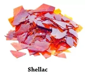
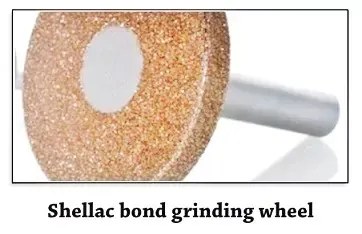
Shellac bonding process:
• Shellac
bonded wheels are also known as elastic bonded wheels.
• In this
process, the abrasive and shellac are mixed in heated containers and then
rolled or pressed in heated moulds.
• Later the
shapes are hacked it few hours at the temperature of approximately 150°C.
• The
elasticity of this bond is greater than in other types and it has considerable
strength.
• It is not
intended for heavy duty.
• Shellac
bond is cool cutting on hardened steel and thin sections, and is used for
finishing chilled iron, cast iron and steel rolls, hardened steel cams and
aluminum pistons, and in very thin sections, for abrasive cutting of machines.
• A shellac
bonded wheel is denoted by the letter 'F'.
 |
Resinoid
bonding process:
• Resinoid
wheels are produced by mixing abrasive grains with synthetic resins and other
compounds.
• Then the
mixture is placed in moulds and heated at about 200°C.
• At this
temperature, the resin sets to hold the abrasive grains in whee] form.
• Wheels
bonded with synthetic resin, such as Bakelite and Redmanol, are used for
purposes which require a strong, free high speed wheel.
• They can
remove stock very rapidly.
• They are
useful for precision grinding cams, and rolls requiring high finish.
• A resinoid
bonded wheel is denoted by the letter B.
Rubber bonding process:
• Rubber
bonded wheels are prepared by mixing abrasive grains with pure rubber and
sulphur.
• Then the
mixture is rolled into sheets, and wheels are punched out of the sheets on a
punch press.
• Following
that, the wheels are vulcanized.
• Rubber
bonded wheels are more resilient, less heat resistant, and more dense than
resinoid bonded wheels.
• They are
used where good finish is primary require.
• They are
strong and tough enough to make extremely thin wheels.
• A rubber
bonded wheel is denoted by the letter R.
Oxy-chloride bonding process:
• This
process consists of mixing abrasive grains with oxide and chloride of
magnesium. The mixing of bond and abrasive is performed in the same way as for
vitrified bonded wheel.
•
Oxy-chloride bonds are employed in making wheels and wheels segments for use in
disc-grinding operations.
•
Oxy-chloride bonds are employed in making wheels and wheels segments for use in
disc-grinding operations.
• The bond
ensures a cool cutting action.
• So
grinding is best done dry.
• An
oxy-chloride bonded wheel is denoted by the letter 'O'.
Grits:
• The grain
or grit number indicates in a general way the size of the abrasive grains used
in making a wheel, or the size of the cutting teeth, since grinding is a true
cutting operation.
• Grain size
is denoted by a number indicating the number of meshes per linear inch [25.4
mm] of the screen through which the grains pass when they are graded after
crushing.
• The
following list shows the of grain ranging from very coarse to very fine, it
includes all the ordinary grain sizes commonly used in the manufacture of
grinding wheels:
• In case
grinding wheels are manufactured from special grain combinations, the grinding
wheel manufacturer may use an additional symbol appended to the standard grain
size number.
Example:
(i) 36 -
Normal standard.
(ii) 36.5 -
Special grain combination.
• The size
of abrasive grain required in a grinding wheel depends on the amount of
material to he removed, the finish desired, and the hardness of the material
being ground.
• In
general, coarse wheels are used for fast removal of materials.
• Fine
grained wheels are used for soft, ductile materials but generally a fine grain
should he used to grind hard, brittle materials.
Grade:
• The term
'grade' as applied to a grinding wheel refers to the tenacity or hardness with
which the bond holds the cutting points or abrasive grains in a place.
• It dose
not refer to the hardness of the abrasive grain.
• The grade
shall be indicated in all bonds and process by a letter of the English
alphabet, A denoting the softest and Z the hardest grade.
• The term
'soft' or 'hard' refer to the resistance of a bond offers to disruption of the
abrasives.
• A wheel
from which the abrasive grains can easily be dislodged is called soft, whereas
one which holds the grains more securely is called hard.
• The grades
are denoted as shown in table below:
• The grade
of the grinding wheel depends on the hardness of the material being ground, the
arc of the contact, the wheel and work speeds, and the condition of the
grinding machine.
• Hard
wheels are recommended for soft materials and soft wheels for hard materials.
Structure:
• Abrasive
grains arc not packed in the wheel but are distributed through the bond.
• The
relative spacing is referred to as the structure and denoted by the number of
cutting edges per unit area of wheel face as well as by number and size of void
spaces between grains.
• The
primary purpose of structure is to provide chip clearance and it may be open or
dense.
• The
structure commonly used is denoted by numbers as shown in table:
• The
structure of a grinding wheel depends on the hardness of the material being
ground, the finish required, and the nature of the grinding operation.
• Soft,
tough and ductile materials and heavy cuts require an open structure, whereas
hard and brittle materials and finishing cuts require a dense structure.
Wheel shapes and factors for wheel selection:
• Grinding
wheels are made in many different shapes and sizes to adapt them for use in
different types of grinding machines and on different classes of work.
• They fall
into the following broad groups;
(i)
Straight-side grinding wheels
(ii)
Cylinder wheels
(m) Cup
wheels
(iv) Dish
wheels.
• The shapes
of grinding wheels have been standardized so that those commonly use in
production and tool room grinding may be designated by a number or name or
both.
• The sizes
of wheels may be referred to a system of key letters so that their dimensional
specifications may be written easily.
Straight wheels:
• No. 1, 5,
and 7 are the kind generally used for cylindrical, centreless, and surface
grinding operations. Wheels of this form vary greatly in size.
• The
diameter and width of face naturally depending upon the class of work for which
the wheel is used and the size and power of the grinding machine.
Tapered face straight wheel:
• No. 4 is
primarily used for grinding thread, gear teeth, etc.
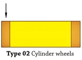
Cylinder or wheel ring:
• No. 2 is
used for producing flat surfaces, the grinding being done with the end face of
the wheel.
Cup wheel:
• No. 6 is
used for grinding flat surfaces by traversing the work past the end or face of
the wheel. Flaring cup whee] No.11 is used for grinding in tool room.
Dish wheel:
• No. 12 is
also used for tool room work. The thinness of the wheel permits it grind the
surface at narrow places. Saucer wheel No. 13 is generally used for sharpening
of circular or band saws. The principal dimensions of a grinding wheel are the
outside diameter, bore diameter, and the width.
Segmented wheels:
• Segmented
wheels are used chiefly on vertical spindle, rotary, and reciprocating- table
surface grinders and way grinders.
• Grinding
wheels of the straight wheel type can be supplied with a large variety of face:
flat, pointed, concave, convex, etc. These faces are used for grinding special
contours and sharpening saws.
Selection of grinding wheels:
• It is
customary for grinding wheel manufacturers to provide, through their published
literature, information on the selection and use of grinding wheels, but it may
not always be possible or convenient for users to take advantage of such
consultative service.
• The need
for ready to use general guide on grinding wheels has been keenly felt and the
Indian Standard (IS: 1249-1958] gives recommendations on the general
considerations which should guide the selection of grinding wheels for
different applications.
• In
selecting a grinding wheel there are four constant factors and four variables;
• Constant
factors:
(i) Material
to be ground
(ii) Amount
of stock to be removed
(iii) Area
of contact.
(iv) Type of
grinding machine
• Variable
factors:
(i) Wheel
speed
(ii) Work
speed
(iii) Condition
of the machine
(iv)Personal
factor
The material to be ground:
(i) Aluminium
Oxide abrasive is recommended for materials of high tensile strength and
silicon carbide for low tensile strength.
(ii) Fine
grain is used for hard and brittle materials and coarse grain for soft ductile
metals.
(iii) Hard
wheel is used for soft materials and soft wheel for hard materials.
(iv) Generally,
close spacing is required for hard and brittle materials and wide for soft and
ductile.
(v) The
class of work usually dictates the bond to be used. Bond selection, of course,
can be safely left to the manufacturers, if the class of work for which the
wheel is required is clearly stated. However, majority of wheels are
manufactured with vitrified bonds.
• Amount of
stock to be removed:
(i) This
involves accuracy and finish.
(ii) Coarse
grain is used for fast cutting and fine grain for fine finish
(iii) Wide
spacing for rapid removal and close for fine finish.
• Resinoid,
rubber, and shellac bond for high finish.
Maintenance of grinding wheel:
• To improve
the cutting capacity.
• To improve
the efficiency of grinding wheel.
• To run the
grinding wheel in concentric speed with spindle.
• The
grinding wheel can be maintained in following ways;
(i) Dressing
(ii) Truing
(iii)
Balancing.
Dressing:
• Dressing
removes loading and breaks away the glazed surface, so that sharp abrasive
particles are again presented to the work.
• This is
done with various type of dressers.
• A common
type of wheel dresser, known as the star-dresser, is shown below.
•
Star-dresser consists of a number of a hardened steel wheels with points on
their periphery.
• The
dresser is held against the face of the revolving wheel and moved across the
face to dress the hole surface.
• This type
of dresser is used to dress coarse-grain abrasive wheels used for rough
snagging work.
• Another
type of wheel dresser consists of a steel tube filled with a bonded abrasive.
• The end of
the tube is held against the wheel and moved across the face.
• The grade
of abrasive in the dresser may vary for different types of dressing operations.
• Abrasive
wheel dressers operates at high speed are frequently used to dress other
wheels.
• They are
used to dress wheels where a fair degree of finish is desired on the work.
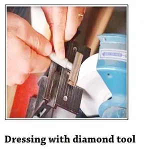
• For
precision and high finish grinding, small industrial diamonds, known in the
trade as bort, are used.
• The
diamond or group of diamonds is mounted in a holder. The diamond should be kept
pointed, since only the point can be used for cutting.
• This is
done by the holder down at a 15° angle and using a new surface each time the
wheel is dressed.
• A good
supply of coolant should he used when dressing with a diamond, as overheating
can causes the diamond to fracture or drop out of its setting.
• Very light
cuts only may be taken with diamond tools.
• This
dressing process may use following dressing tools;
(i) Cluster
type tool: Used for roughing and commercial finishes.
(ii)
Corrugated disc dressers: Made of special alloy steel, used for superior
finish.
(iii) Disc
dressers: Steel disc with teeth used for medium grade roughing wheels and for
cam and crank shaft grinding wheels.
Truing:
• Truing is
the process of changing the shape of the grinding wheel as it becomes worn from
an original shape, owing to break away from the abrasive and bond.
• This is
done to make the wheel true and concentric with the bore, or to change the face
contour for form grinding.
• Truing and
dressing are done with the same tools, but not for the same purpose.
• The only
satisfactory method of truing a wheel is by the use of a diamond tool in a
similar manner as explained before.
• In turning
a wheel with a diamond, the feed rate must not exceed 0.02 mm, otherwise
grooves may be cut into the wheel.
• More
popular is form-truing with a crushing roll. In this, a roll, shaped to the
desired profile, is forced against the revolving wheel, crushing the
corresponding shape into it.
• Rolls may
be of two types: Idler in which the wheel drives the roll; and Power driven, in
which a small motor drives the roll which, in turn, rotates the wheel by
frictional contact.
• Wheels
trued by crushing cut faster and run cooler than those trued with a diamond.
• Crushing
produces a wheel with many sharp pointed grains, while diamond truing tends to
produce many grains with flat surfaces.
Balancing:
• If wheels
become out of balance through wear and cannot be balanced by truing or
dressing, they should be removed from the machine and discarded.
• Wheels
should be tested for balance occasionally and rebalanced if necessary.
• Wheels
that are out of balance not only produce poor work but may put under strains on
the machine.
• Small
wheels may be balanced by milling a short recess on the inside of the flanges
and filling with lead.
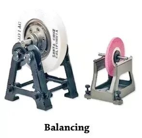
• Large
wheels should he placed on a balancing stand and balanced by moving weights
around a recessed flange.
•
Now-a-days, grinding wheel mounts are provided with devices to enable balancing
to be done whilst the wheel is running and between grinding operations.














0 Comments