Computer Numerical Control Machine (Advantages, Disadvantages, Working Principle), Recirculating ball screw and nut & Automatic Tool Changer with Working
Development of CNC machines:
Due to invention of small sized computers during 1960s and
1970s, led to development of CNC machines. In CNC the MCU of NC machine is replaced by a computer.
Punched tape may be used only once. Program can be stored in the computer and
can be recalled any time and any number of times. With the development of
digital computers, the design of NC systems has changed dramatically and has
paved to:
• Computer Numerical Control [CNC]
• Direct Numerical Control [DNC]
• Adaptive Control.
Computer numerical control machines:
A computer numerical control is a NC system that utilizes a
dedicated computer to perform all basic numerical control functions.
Advantages of CNC Machines over NC Machines:
• More flexibility:
It is more flexible in the sense that modifications can be
made to the program rather than making completely new tape as with older
conventional NC systems.
• Reduced data reading error:
The weakest link is least used i.e. the tape is read only
once and the program is stored in the memory for repetitive machining.
• Online editing of program:
If there is any mistake in dimension, cutting conditions,
and cutter compensation then it can be easily modified by the part data stored
in computer memory rather than sending the tape for re-processing.
• Diagnostic:
It can diagnose program, and can detect the machine
malfunctioning even before the part is produced.
• Conversion of units:
If the tapes are prepared in the units of inches then the
same system of units can be converted into S.I. units within the computer
memory.
• Integration with DNC systems:
It can be integrated with DNC systems in highly
sophisticated manufacturing systems.
Disadvantages of CNC machines:
• High initial cost:
The initial equipment cost and its installation cost is
higher than the conventional machine because it uses a complex
electro-mechanical technology.
• Higher maintenance cost:
Personnel, trained in electronics along with mechanical and
electrical, are required to service and maintain these complex machines.
• Skilled CNC personnel:
It is very difficult to find a skilled programmer and
operator for a CNC, hence existing personnel must be trained in the programming
and operation. Machines have to be installed in air-conditioned places.
Direct Numerical Control [DNC]:
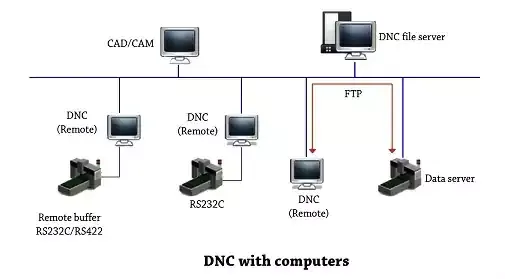
Direct Numerical Control [DNC] can be defined as a
manufacturing system in which a number of machines are controlled by a single
computer through direct connections and in real time. Typically one large
computer can manage few hundred machine tools.
On some CNC machine controllers,
the available memory is too small to contain the machining program [for example
machining complex surfaces], so in this case the program is stored in a
separate computer and sent directly to the machine, one block at a time. If the
computer is connected to a number of machines it can distribute programs to
different machines as required. Usually, the manufacturer of the control
provides suitable DNC software. However, if this provision is not possible,
some software companies provide DNC applications that fulfill the purpose. DNC
networking or DNC communication is always required when CAM programs are to run
on some CNC machine control.
Advantages of DNC machine:
• Control of one machine at a time.
• Remote control of machines is possible.
• Elimination of tape and tape reader.
• DNC software helps in managing the part programs in a
better and easier way.
• Greater computational capability and flexibility.
• Establishes the framework for the evolution of the
future.
Block diagram of CNC system:
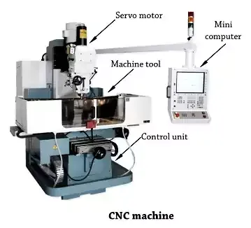
The principal components of CNC machine are:
• Tape reader for initial program entry
• Mini/ Micro computer 81 NC part programming
• Computer hardware interface 81 servo system
• Machine tool.
Working principle of CNC system:
CNC is a microprocessor based control system that accepts a
set of program instructions from the punched tape or input part program,
processes and sends output control information to a machine tool. The
information stored in the computer can be read by automatic means and converted
into electrical signals, which operate the electrically controlled servo
systems. Electrically controlled servo systems permits the slides of a machine
tool to be driven at the appropriate feeds and direction so that complex shapes
can be cut, often with a single operation and without the need to reorient the
work piece. Computer numerically control can be applied to milling machines,
lathe machines, grinding machines, boring machines, flame cutters, drilling
machines etc.
Some Components of CNC
Recirculating ball screw and nut:
In the CNC machines, the conventional design of lead screw
and its nut assembly is not used because of its lesser power transmission,
great inaccuracy due to backlash and action of higher rate of frictional forces
due to sliding motion of the parts.
To avoid the above difficulties;
The recirculating ball screw and nut assembly is used which
is very high efficient in working, reversible in operation, lesser wear and
tear, longer working life and without stick slip action.
The use of balls gives rolling motion instead of sliding
motion which minimise the frictional forces near to zero value. These, are used
in CNC to convert rotary motion of motor and screw into linear motion of slide.
Ball screw introduces a series of bearing balls between screw and nut. Rolling
of balls in the groove replaces the sliding friction of acme screws. Rolling
balls exit from trailing end of nut and picked up by an outside return tube
which put it at the leading end of nut.
Obviously, there must be balls in each thread within the nut.
To unable the movement of the carriages [work tables] to be bidirectional
without any significant errors in position occurring, there must be a minimum
of backlash in the screw and nut. One method of achieving virtual zero backlash
with these screws is by fitting two nuts.
Automatic Tool Changer
Tool magazine:
Tool magazines to be used have to be considered in terms of
the following attributes.
• Storage capacity
• Type and shape
• Tool-change procedure
Storage capacity typically starts with about 12 and can go
as high as 200. The simplest type of too] magazine is a turret as shown in
figure.
This method combines tool storage with the tool changing
procedure, without the need for a tool change arm[gripper]. The turret
simply-indexes to bring the tool into the position of machining, since the
spindle is combined with the tool turret as shown in figure.
The next type of tool magazine found in most of the machine
tools are drum or disc-type magazines. A typical drum-type tool magazine is
shown in figure.
The drum rotates for the purpose of tool change to bring the
required tool to the tool change arm. In drum type, as the number of tools in
the magazine increases, its diameter also increases. For storing large number
of tools, a chain-type tool magazine provides the necessary flexibility. A
typical chain-type magazine in a simple configuration is shown in figure.
Working of automatic tool changer:
The simplest of the true tool-changing mechanisms is the 180
degree rotation tool changer [gripper] shown in figure.
Upon receiving a tool change command, the machine control
unit sends the spindle to its fixed tool change coordinates. At the same time,
the tool magazine is indexed to the proper position. The tool changer then
rotates and engages both the tool in the spindle and the tool in the magazine
at the same time. The drawbar is removed from the tool in the spindle and the
tool changer removes both tools from their respective places. The tool changer
then rotates 180 degrees and swaps the tool that was in the spindle with the
one that was in the magazine. While the tool changer is rotating, the magazine
repositions itself to accept the old tool that was removed from the spindle.
The tool changer then installs the new tool in the spindle and the old tool in
the magazine. Finally, the tool changer rotates back to its "Parked"
position where it remains until needed. The tool change is thus complete and
the program continues.
END


0 Comments